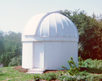
 Cassel
Observatory is a 15.5' domed structure built in 1990. All observatory functions
including door and dome movement, lighting, alarm system, CCD imaging, and
telescope tracking are computer controlled. Two Pentium-based computers provide
the processing power necessary to run the observatory. Disk Storage is
maintained by a Windows 2000 server maintained in the residence on the property.
Cassel
Observatory is a 15.5' domed structure built in 1990. All observatory functions
including door and dome movement, lighting, alarm system, CCD imaging, and
telescope tracking are computer controlled. Two Pentium-based computers provide
the processing power necessary to run the observatory. Disk Storage is
maintained by a Windows 2000 server maintained in the residence on the property.
The following are a sequence of pictures taken during the construction
process along with a brief description: (Click on the thumbnail for the full
size picture).
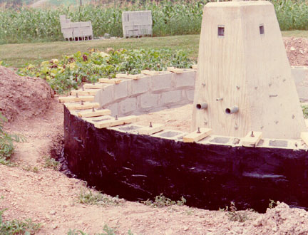
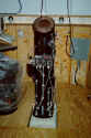
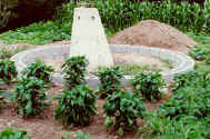 Construction
began with excavation of a 10' deep hole. This provided the foundation for the
telescope pier seen here in the picture. A circular foundation was dug, a
concrete footer was poured, and the foundation wall of 10" concrete blocks
were laid. The inside corners of the blocks were chipped away to allow the
circular wall to be formed. You can see that the observatory was constructed in
the middle of what used to be a vegetable garden. The top of the concrete pier
that you see is the heighth of the finished observatory floor.
Construction
began with excavation of a 10' deep hole. This provided the foundation for the
telescope pier seen here in the picture. A circular foundation was dug, a
concrete footer was poured, and the foundation wall of 10" concrete blocks
were laid. The inside corners of the blocks were chipped away to allow the
circular wall to be formed. You can see that the observatory was constructed in
the middle of what used to be a vegetable garden. The top of the concrete pier
that you see is the heighth of the finished observatory floor.
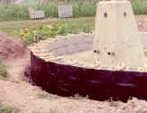 After
the wall was complete, a sealer was applied to the exterior surface and bolts
were set in concrete to provide a secure place to fasten the wall base plate. A
concrete floor was later poured.
After
the wall was complete, a sealer was applied to the exterior surface and bolts
were set in concrete to provide a secure place to fasten the wall base plate. A
concrete floor was later poured.
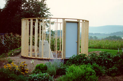
 The
walls are constructed of standard 2x6's. The base and top rings were made by
cutting arcs from 3/4" plywood, and then gluing and screwing them together
to achieve the 15' circle. Holes were drilled in the lower ring to match the
bolts in the foundation. This picture also shows the entrance door in place.
The
walls are constructed of standard 2x6's. The base and top rings were made by
cutting arcs from 3/4" plywood, and then gluing and screwing them together
to achieve the 15' circle. Holes were drilled in the lower ring to match the
bolts in the foundation. This picture also shows the entrance door in place.
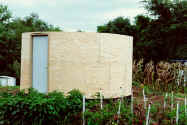 This
photo shows the walls after the 1/4" plywood was applied. In order to allow
bending, the wood was soaked with water and curved over the structure while
still wet.
This
photo shows the walls after the 1/4" plywood was applied. In order to allow
bending, the wood was soaked with water and curved over the structure while
still wet.

Standard white vinyl soffit was used to side the structure. The
upper and lower trim moldings were curved and applied as the soffit was
installed.
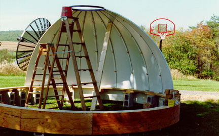
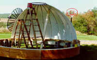 Another
laminated plywood ring was made to support the dome. Here the dome is partially
assembled on the ring. Note the plywood skirt which will later be covered with
soffit. The actual dome is a new silo roof! I decided to use this after finding
the price of commercially available domes to be astronomical (no pun intended).
Another
laminated plywood ring was made to support the dome. Here the dome is partially
assembled on the ring. Note the plywood skirt which will later be covered with
soffit. The actual dome is a new silo roof! I decided to use this after finding
the price of commercially available domes to be astronomical (no pun intended).
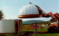 My
father's farm tractor and front-end loader were used to place the dome on the
observatory. You can see the industrial casters that were mounted on the
building to support the dome. After the dome was in place, I was pleased to see
that it could be rotated with one hand. Additional casters were later installed
to prevent lateral movement of the dome.
My
father's farm tractor and front-end loader were used to place the dome on the
observatory. You can see the industrial casters that were mounted on the
building to support the dome. After the dome was in place, I was pleased to see
that it could be rotated with one hand. Additional casters were later installed
to prevent lateral movement of the dome.
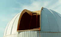 After
the dome was in place, the opening for the shutter doors was cut and framed with
3/4" plywood. As with the plates used on the walls, the plywood was
laminated with glue and screws.
After
the dome was in place, the opening for the shutter doors was cut and framed with
3/4" plywood. As with the plates used on the walls, the plywood was
laminated with glue and screws.
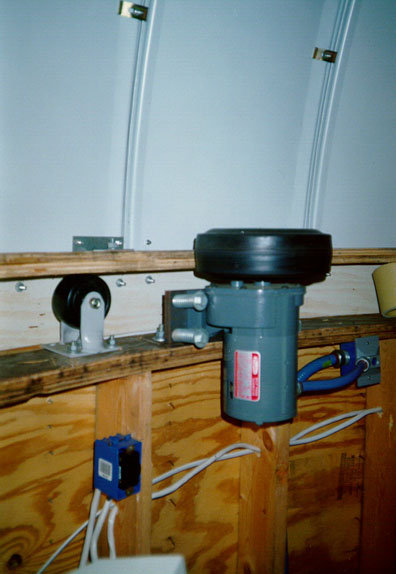
 This
photo shows the drive motor used to rotate the dome. It is a inflated rubber
tire mounted on a bi-directional slow speed geared motor. The tire is held
against the dome ring by a spring mechanism. Activating the motor rotates the
dome at approximately 1 r.p.m in either direction
This
photo shows the drive motor used to rotate the dome. It is a inflated rubber
tire mounted on a bi-directional slow speed geared motor. The tire is held
against the dome ring by a spring mechanism. Activating the motor rotates the
dome at approximately 1 r.p.m in either direction
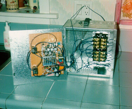
 This
is an example of one of the relay boxes used to control the observatory
functions. Several of these devices mounted in the crawl space allow computer
control of the dome drive, shutter doors, all interior and exterior lighting,
and the alarm system.
This
is an example of one of the relay boxes used to control the observatory
functions. Several of these devices mounted in the crawl space allow computer
control of the dome drive, shutter doors, all interior and exterior lighting,
and the alarm system.
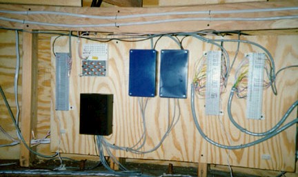
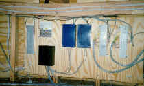 This
is the crawl space mounted interface between the relay boxes (pictured above)
and the low voltage relay cards in the control computer.
This
is the crawl space mounted interface between the relay boxes (pictured above)
and the low voltage relay cards in the control computer.
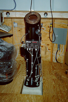
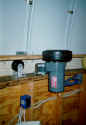
 The
telescope is mounted on a custom pier fabricated by a local machine shop. You
can see the pier in this photo along with the telescope drive corrector and CCD
camera control box. Also, the wood observing floor is visible in this picture.
The
telescope is mounted on a custom pier fabricated by a local machine shop. You
can see the pier in this photo along with the telescope drive corrector and CCD
camera control box. Also, the wood observing floor is visible in this picture.
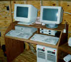 Here
are the two computers used in the observatory. Pentium computers control the
observatory functions, telescope tracking and the CCD imaging camera and
tracking system. This photo was taken before the drywall was installed.
Here
are the two computers used in the observatory. Pentium computers control the
observatory functions, telescope tracking and the CCD imaging camera and
tracking system. This photo was taken before the drywall was installed.
A Microsoft Windows NT® server in the residence supports the observatory
computers. An Ethernet Lan serves as the network communication backbone.
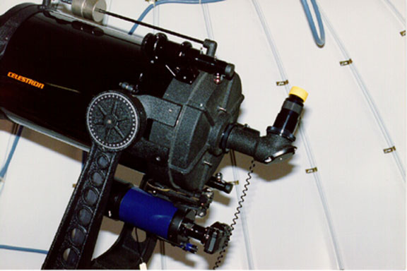
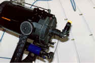 This
is the Celestron C-14 telescope mounted in the observatory. The_Sky® software
from Software Bisque is used to track the telescope movement. A Meade 2045 SCT
is mounted to the main scope with a tangent assembly and is used for tracking
and astrophotography. A SBIG ST-4 is used for autoguiding and imaging.
This
is the Celestron C-14 telescope mounted in the observatory. The_Sky® software
from Software Bisque is used to track the telescope movement. A Meade 2045 SCT
is mounted to the main scope with a tangent assembly and is used for tracking
and astrophotography. A SBIG ST-4 is used for autoguiding and imaging.